← Micro:bit

Chapter 1

Getting to Know micro:bit V2

รู้จักกับ micro:bit V2

  • The micro:bit V2 is a pocket-sized computer (4 × 5 cm) designed by the BBC and its partners to teach coding, computational thinking (วิทยาการคำนวณ) and physical computing.
  • A microcontroller (ไมโครคอนโทรลเลอร์) runs your code directly on the hardware. There is no external monitor.
  • It controls lights, a speaker, touch sensors, motion sensors and 2.4 GHz radio, all in your hand.

Introduction & Background บทนำและที่มาของ micro:bit

  • In 2016 the BBC and 29 partners (ARM, Microsoft, Nordic Semiconductor, Lancaster University and others) made the first micro:bit.
  • The goal: give every Year 7 student in the UK their own programmable computer.
  • In late 2020 the micro:bit V2 arrived: more power and memory, plus a speaker, a microphone and a touch logo.
2016 late 2020 micro:bit V1 BBC + 29 partners for UK Year 7 students micro:bit V2 4× the processing power and memory + speaker, microphone, touch logo
Timeline: the original board in 2016, then V2 in late 2020.

What is a microcontroller board? ไมโครคอนโทรลเลอร์

INPUTS Buttons A and B Touch logo Microphone Motion + compass Radio (receive) nRF52833 runs your code 64 MHz OUTPUTS 5 × 5 LED matrix Speaker Radio (send) Pins to other parts
Inputs tell the board what is happening, your code decides, and outputs act on it.

What can you create?

Games dice, stickmananimation,Rock-Paper-Scissors Audio and music Star Wars theme,wedding march,Pink Panther Smart sensors clap counter,compass,spirit level,thermometer Wireless pagers,treasure hunt,quiz clicker Analog battery voltagetester withcrocodile clips
Five kinds of projects you will build in this course.
  • Interactive games: rolling digital dice, Rock-Paper-Scissors, animated stickmen.
  • Audio and music: Star Wars themes, a wedding march, motion-reactive Pink Panther tunes.
  • Smart sensors: clap counters, 360° compasses, 2D spirit levels, thermometers.
  • Wireless gadgets: two-way pagers, treasure-hunt beacons, classroom quiz clickers.
  • Analog electronics: real-time battery voltage testers with crocodile-clip probes.
  • Textbook: this course follows "แรกเริ่มเขียนโค้ดกับ micro:bit V2" (Getting Started Coding with micro:bit V2) by Kritsada Chaiyen & Natee Kasemchotiphun, published by INEX, ISBN 978-616-7597-50-8.
Next: 1.1 Hardware Specifications →

1.1 Hardware Specifications คุณสมบัติของ micro:bit V2

  • The V2 board is only 4 × 5 cm but packs inputs, outputs and sensors.
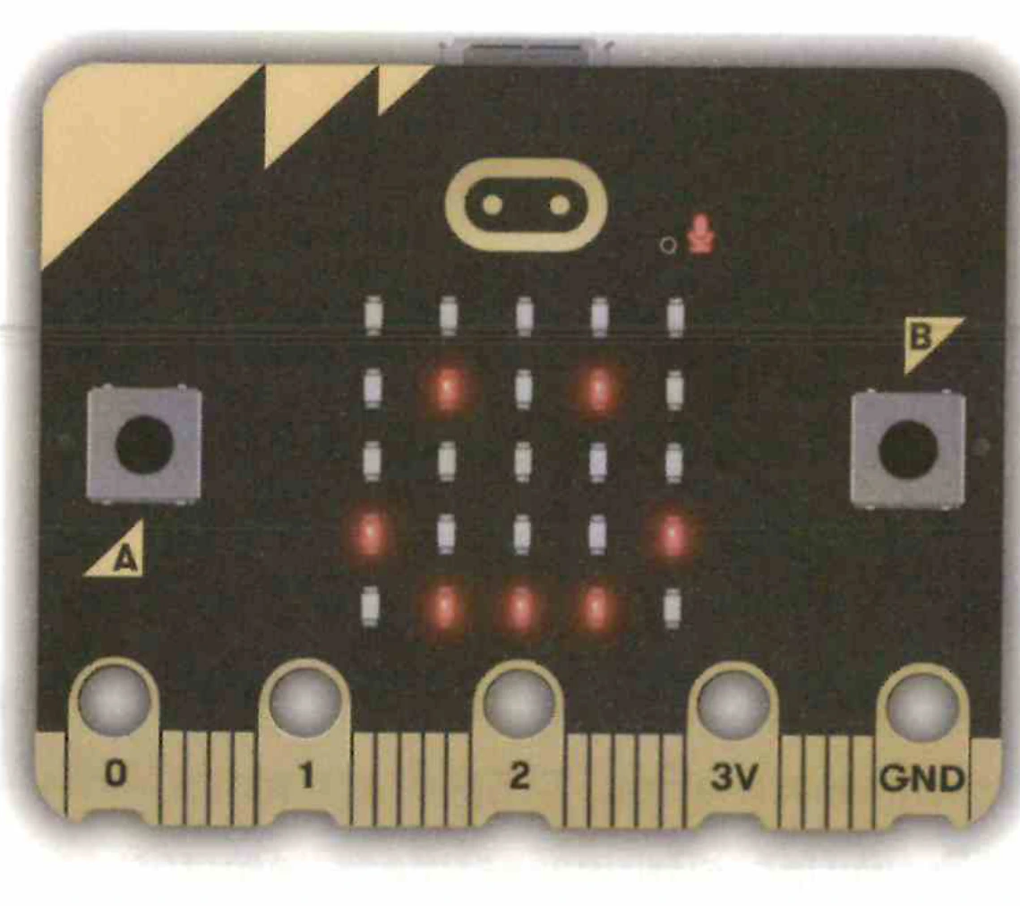
  • First the labelled drawings below, then hover or tap the real photos to see what each part does.

Front of the board

A B 1 2 3 4 5 6 7 1 microUSB port power, code, WebUSB 2 Touch logo capacitive, no GND needed 3 Microphone hole + LED LED lights when listening 4 Button A left 5 Button B right 6 5 × 5 LED matrix 25 red LEDs 7 Ring pins 0, 1, 2, 3V, GND 4 mm holes for clips
Front view: seven parts to know.

Back of the board

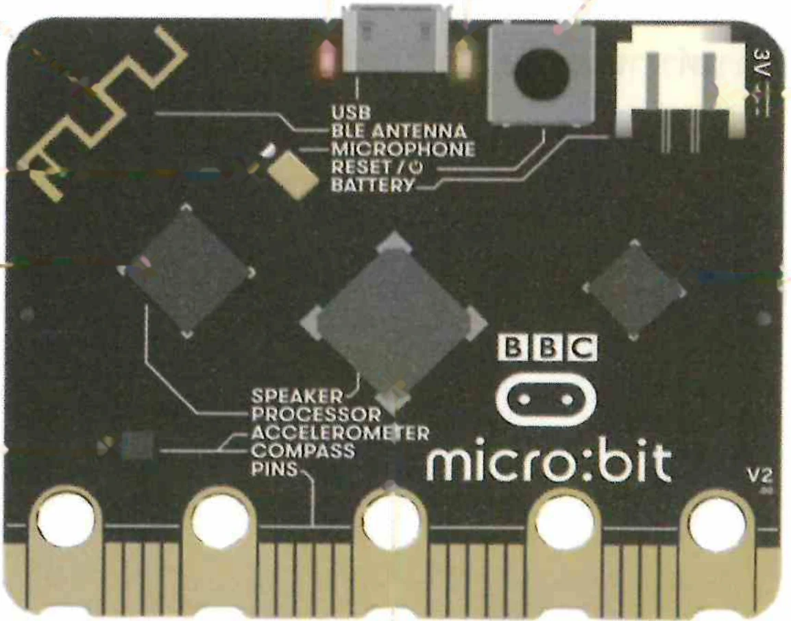
1 2 3 4 5 6 7 8 9 10 11 12 1 Radio / Bluetooth antenna 2 nRF52833: main chip (your code) 3 MEMS microphone 4 LSM303AGR: motion + compass 5 Piezo speaker 6 Power LED (red) 7 microUSB port 8 USB LED (yellow) 9 Reset / power button 10 JST battery socket (3 V) 11 KL27Z: USB chip 12 Edge connector (25 pins)
Back view: the chips and connectors.
🔍

micro:bit V2 Front View

Interactive Map
Real micro:bit V2 Front View
👉

Hover or tap any part on the front of micro:bit V2 (Logo, Mic hole, Buttons, 5x5 LED Matrix, or Ring Pins) to explore.

🔍

micro:bit V2 Back View

Interactive Map
Real micro:bit V2 Back View
👉

Hover or tap any component on the back of micro:bit V2 (nRF52833 CPU, Piezo Speaker, MEMS Mic, KL27Z, or Antenna) to explore.

How the parts talk to each other

Computer USB KL27Z USB interface nRF52833 main chip + radio LED matrix Buttons A, B Touch logo + pins Microphone Speaker Motion + compass
The KL27Z chip connects the computer to the main chip; the main chip drives everything else.

Detailed specifications

64 MHz Cortex-M4F + FPU 512 kB flash (programs) 128 kB RAM (working memory) ~270 mA for accessories
The numbers to remember about the V2 board.
  • Main microcontroller: Nordic nRF52833, 32-bit ARM Cortex-M4F at 64 MHz with a hardware floating-point unit, 512 kB flash and 128 kB RAM.
  • USB interface and flashing: NXP KL27Z chip for the computer link, the MICROBIT drive and WebUSB.
  • Motion and compass: STMicroelectronics LSM303AGR, 3-axis accelerometer (±2 g) and 3-axis magnetic compass.
  • Edge connector: 25 contacts: 5 large 4 mm ring holes (pins 0, 1, 2, 3V, GND) for crocodile clips and banana plugs, plus 20 thin gold strips.
  • Display: 5 × 5 red LED matrix (25 LEDs). 9 of them also work as an ambient light sensor.
  • Power in: +5 V from microUSB, or +3 V from the 2-pin JST battery socket on the back.
  • Current for accessories: the V2 regulator gives 300 mA; the board uses about 30 mA itself, leaving about 270 mA for accessories (V1: 90 mA).

📘 Book correction

  • The book says the edge connector has 20 pins.
  • The official micro:bit hardware spec counts 25: the 5 big rings plus 20 thin strips.
  • The book counted only the thin strips.
microUSB cable +5 V JST battery socket +3 V (2 × AAA or AA) micro:bit V2 power LED = on Accessories via 3V and GND pins about 270 mA
Two ways to power the board, and how much current it can give to parts you add.

Edge connector and ring pins

0 1 2 3V GND I/O + touchI/O + touchI/O + touch 0 V +3.3 V edge connector, seen from the front
The five big ring holes can hold a crocodile clip or a 4 mm banana plug; the 20 thin strips between them make 25 contacts in all.

New in V2 compared with V1 (ความสามารถที่เพิ่มเติมจากรุ่นแรก)

V1 (resistive) pin 0 + other hand on GND V2 (capacitive) finger on the gold logo only
Touch sensing: V1 needed your other hand on GND to complete a circuit; V2 senses the finger by itself.
  • Onboard MEMS microphone: SPU0410LR5H-QB-7, with a front sound hole and a red indicator LED.
  • Built-in piezo speaker: plays melodies, chimes and tones with no wiring.
  • Capacitive touch logo: senses a finger with no ground connection.
  • Capacitive ring pins: pins 0, 1 and 2 also sense touch.
  • Power and USB LEDs: red shows power; yellow shows USB data being written.
  • Low-power sleep mode: long-press Reset to power down when running from the JST battery.

V1 against V2

Clock speed V1: 16 MHz V2: 64 MHz Flash memory V1: 256 kB V2: 512 kB RAM V1: 16 kB V2: 128 kB Accessory current V1: 90 mA V2: 300 mA
V2 is the full bar. V1 is drawn to the same scale, so you can see how much each value grew.
Specification micro:bit V1 micro:bit V2 (This Course)
Main Processor Nordic nRF51822 (ARM Cortex-M0 @ 16 MHz) Nordic nRF52833 (ARM Cortex-M4F @ 64 MHz + FPU)
Flash Memory 256 KB 512 KB (2× capacity)
RAM Memory 16 KB 128 KB (8× capacity)
Built-in Speaker None (required external buzzer) Onboard Piezo Speaker included
Microphone None SPU0410LR5H-QB-7 MEMS Mic + LED
Touch Sensing Resistive only (needed circuit to GND) Capacitive Touch Gold Logo + Pins 0, 1, 2
Accessory Current 90 mA maximum About 270 mA for accessories (300 mA regulator)
USB Interface NXP KL26Z NXP KL27Z with WebUSB support

Next: 1.2 Coding Tools →

1.2 Coding Tools รู้จักเครื่องมือเขียนโค้ด

  • The book shows several coding tools, so every student can pick one that fits their level and computer.

Starting at microbit.org

microbit.org "Let's code" MakeCode (blocks) Python Editor (text) Ready-made projects
From microbit.org you can choose blocks (MakeCode) or text (Python), or open a ready-made project.
  • Go to https://microbit.org and open the "Let's code" menu.
  • Choose block coding (Microsoft MakeCode) or text coding (Python Editor).
  • You can also try beginner projects such as Beating heart, Emotion badge and Dice.

1.2.1 MakeCode Online

  • Open https://makecode.microbit.org.
  • New project: click the big + New Project button.
  • Existing code: click Import (นำเข้าโค้ดที่มีอยู่แล้ว) to see 3 options (below).
  • Create a project window: type a name (for example Example1). Code options lets you pick the language set.
Import Import File... (.hex or blocks file) Import URL... (shared project link) Your GitHub Repo... Code options: Blocks, JavaScript and Python Python only JavaScript only
The Import button offers three sources; the Code options list offers three language sets.

The MakeCode user interface

MakeCode Blocks JavaScript Python Download 1 Simulator ▶ ↻ debug 2 Palette Basic Input Music Led Radio Loops Logic, Variables, Math, ... 3 Workspace on start forever show icon drag blocks here and snap them together
Three core areas: the simulator on the left, the block palette in the middle and the workspace on the right.
  1. micro:bit simulator (บอร์ดจำลอง): a live virtual board on the left.
  2. Block palette (หมวดหมู่ของบล็อกคำสั่ง): Basic, Input, Music, Led, Radio, Loops, Logic, Variables, Math, Advanced.
  3. Workspace (พื้นที่เขียนโค้ด): drag, snap and join colour-coded blocks.
  • At the top centre, switch between Blocks, JavaScript and Python.
  • You see the same program written three ways.
Blocks show string "Hi" JavaScript basic.showString("Hi") Python basic.show_string("Hi") = =
One program, three views. Press the toggle at the top and the editor rewrites it for you.

1.2.2 MakeCode Offline App

MakeCode Online Runs in the browser Needs internet makecode.microbit.org Always the latest version WebUSB (Chrome / Edge) MakeCode Offline app Installed on the computer Works without internet Windows or macOS Good for weak school Wi-Fi Same blocks and simulator
Online or offline: the same blocks, palette and simulator.
  • No reliable internet in class? Download the app from https://makecode.microbit.org/offline-app.
  • Windows: makecode-microbit-setup-win64.exe.
  • macOS: makecode-microbit-mac64.zip.
  • It has the same interface, block categories and simulator as the web version.

1.2.3 micro:bit Simulator & Debugger Mode

  • Test your project in the simulator before you flash the real board.
  • Interactive parts: click Button A, Button B and the virtual A+B; tap the gold logo; click virtual pins 0, 1, 2.
Play Play / Pause start or pause the program Restart Restart reboot run on start again Bug Debug step through the code Mute Mute sound on or off Full Fullscreen fill the window
The five simulator controls.
  • Play / Pause: start or pause the simulator.
  • Restart: reboot and run on start again.
  • Debug mode (ดีบักโหมด): click the bug icon to watch how the program runs.
  • Audio mute: switch simulator sound on or off.
  • Fullscreen: make the simulator fill the window.

Debug mode

Blocks (slow-motion trace) on start show string "GO" show number 1 yellow outline = the block running now Step Play one block at a time / full speed Variables panel score = 3 live values stored in RAM Step: go forward one block Play: resume
In debug mode the active block glows, you advance with Step, and the variables panel shows the values in RAM.
  • Step (เล่นทีละส่วน): run one block at a time.
  • Play: go back to normal speed.
  • Variables panel: live values of your variables, kept in RAM.
  • Slow-motion tracing: the running block glows.

Try the simulator right here

  • Test your first program on this page before sending code to a real board. It is the same program you would build in MakeCode.
  • Press ▶ Run. on start scrolls HELLO once, then forever beats the heart again and again.
on start HELLO ← scrolls once forever show icon heart + pause 200 show icon small heart + pause 200 ↻ repeat
What you will see: HELLO scrolls once, then two heart pictures take turns (about 0.8 s each) for ever.
show icon (heart)
show icon (small heart)

💻 Your first program — does the board work?

on start
show string HELLO
forever
show icon
pause (ms) 200
show icon
pause (ms) 200
See it in JavaScript
basic.showString("HELLO")
basic.forever(function () {
	basic.showIcon(IconNames.Heart)
	basic.pause(200)
	basic.showIcon(IconNames.SmallHeart)
	basic.pause(200)
})

on start versus forever

  • on start runs once when the board powers on.
  • forever repeats again and again.
  • Run it: GO appears once, then 1 → 2 → 3 keeps repeating. Press ■ Stop to halt the board.
GO 1 2 3 1 2 3 … on start: once forever: repeats until power off
The order of events: GO appears one time only; the 1, 2, 3 loop never ends.

💻 on start runs once · forever runs again and again

on start
show string GO
forever
show number 1
show number 2
show number 3
See it in JavaScript
basic.showString("GO")
basic.forever(function () {
	basic.showNumber(1)
	basic.showNumber(2)
	basic.showNumber(3)
})

Next: 1.3–1.4 USB & WebUSB Flashing →

1.3 & 1.4 Loading Code onto the Board

  • There are two ways to send a compiled program to the real board.
MakeCode Method 1: manual Download .hex → copy it onto the MICROBIT drive Method 2: WebUSB Pair once → Download writes to the board in one click
Two routes from MakeCode to the board.

Method 1: Manual flashing via the USB flash drive (การใส่โค้ดลงบอร์ด)

Write code MakeCode blocks Download purple button .hex file saved on the PC Copy to drive MICROBIT drive Board runs it yellow LED stops
The manual route: write code, download a .hex file, drop it on the MICROBIT drive, the board runs it.
  1. Step 1 — Connect the cable: plug a microUSB cable between the micro:bit and the computer. The red power LED and yellow USB LED light up.
  2. Step 2 — Find the drive: the PC mounts a drive named MICROBIT, holding DETAILS.TXT and MICROBIT.HTM.
  3. Step 3 — Download: in MakeCode, click the purple Download button (or the disk icon).
  4. Step 4 — Copy the hex: save or drag the .hex file into the MICROBIT drive.
  5. Step 5 — Wait for the LED: the yellow USB LED on the back flashes fast. When it stops, your code runs at once.
Red LED steady on = board has power Yellow LED fast flashing = writing code stops = code is running on the back of the board
The two small LEDs on the back tell you what the board is doing over USB.

⚠️ Warning while plugging in the cable ข้อควรระวังขณะเสียบสาย microUSB

  • Do not hold the RESET button while you plug in the microUSB cable.
  • Holding it starts MAINTENANCE mode.
  • If it happens by accident, unplug the USB cable and plug it in again.

Method 2: One-click direct flashing with WebUSB (การจับคู่อุปกรณ์ Pair device)

  • WebUSB lets MakeCode write straight to the board from the browser. No file moving.
1 Operating system Windows 10/11 or macOS 2 Browser Google Chrome or Microsoft Edge only 3 Firmware DAPLink version 0249 or higher
Three things must all be true before WebUSB will work.

WebUSB prerequisites (ข้อกำหนด)

  1. Operating system: Windows 10/11 or macOS.
  2. Browser: Google Chrome or Microsoft Edge only.
  3. Firmware: DAPLink version 0249 or higher.

5-step WebUSB pairing (ขั้นตอนการใช้ WebUSB)

1 2 3 4 5 Download ⋯ click the three dots Pair device choose it in the menu Pair device press it in the help popup BBC micro:bit CMSIS-DAP Connect pick the board in the browser box Download flashes at once Bonus: the "Show console Device" button appears for live serial data and graphs.
Pairing wireframes: the three dots, the popup, the browser's device list, then one-click Download.
  1. Step 1 — Open the menu: click the three dots (...) beside the Download button.
  2. Step 2 — Choose Pair device: pick Pair device in the popup menu.
  3. Step 3 — Confirm: click the Pair device button in the help window.
  4. Step 4 — Select the board: in the browser box choose BBC micro:bit CMSIS-DAP (or DAPLink CMSIS-DAP), then click Connect.
  5. Step 5 — Download: now Download flashes the board instantly. The Show console Device button also appears for live serial graphs.
Manual .hex copy Works in any browser Move a file every time No setup needed No serial console WebUSB Chrome or Edge only Pair once, then 1 click Needs firmware 0249+ Show console Device
Manual copy against WebUSB.

Next: 1.5 Firmware Maintenance →

1.5 micro:bit Firmware เฟิร์มแวร์ของ micro:bit

  • Firmware is the low-level system program on the NXP KL27Z interface chip.
  • It manages the computer link, the USB drive and DAPLink bootloading.
Computer KL27Z chip holds the FIRMWARE USB drive, WebUSB, DAPLink nRF52833 chip holds YOUR PROGRAM the .hex you flashed
Two programs live on the board: your code on the nRF52833, and the firmware on the KL27Z.

1.5.1 Checking the firmware version (การตรวจสอบเฟิร์มแวร์)

MICROBIT drive DETAILS.TXT read Interface Version 0249 or higher WebUSB works below 0249 update the firmware
Check the version in DETAILS.TXT, then decide whether to update.
  1. Step 1 — Open the drive: connect the board by USB and open the MICROBIT drive.
  2. Step 2 — Find the files: DETAILS.TXT (hardware version, interface version, unique ID) and MICROBIT.HTM (a web shortcut to microbit.org).
  3. Step 3 — Read the version: open DETAILS.TXT in Notepad and find Interface Version.
  4. Step 4 — Compare: a number below 0249 means update, to enable WebUSB.
# DAPLink Firmware - see https://mbed.com/daplink
Unique ID: 9904360258434e45005a401000000054000000009796990b
HIC ID: 9796990b
Interface Version: 0255
Bootloader Version: 0255
USB Interfaces: MSD, CDC, HID, WebUSB
Unique ID: 9904360258434e45... Interface Version: 0255 Bootloader Version: 0255 USB Interfaces: MSD, CDC, HID, WebUSB ← check this number
Reading DETAILS.TXT: look at the Interface Version line. Here it is 0255, which is above 0249, so WebUSB works.

1.5.2 How to update the firmware (การติดตั้ง Firmware)

Hold RESET USB unplugged Plug in USB keep holding MAINTENANCE drive appears Copy firmware .hex file MICROBIT board restarts
MAINTENANCE mode: hold Reset while plugging in, copy the firmware .hex, and the board returns as MICROBIT.
  1. Step 1 — Hold Reset: unplug USB, then press and hold the RESET button on the back.
  2. Step 2 — Plug in: keep holding RESET and plug the microUSB cable into the computer.
  3. Step 3 — See the drive: a drive named MAINTENANCE appears instead of MICROBIT.
  4. Step 4 — Copy the firmware: drag the official firmware file onto the drive (see the table below).
  5. Step 5 — Wait and check: the board restarts as MICROBIT. Open DETAILS.TXT again to confirm the new version.
micro:bit V2 0255_kl27z_microbit _0x8000.hex micro:bit V1 0254_kl26z_microbit _0x8000.hex
Pick the firmware file that matches your board.
  • micro:bit V2: 0255_kl27z_microbit_0x8000.hex
  • micro:bit V1: 0254_kl26z_microbit_0x8000.hex

Next: Chapter Review & Self-Check →

Chapter 1 Summary

1.1 Hardware nRF52833, sensors, pins 1.2 Tools MakeCode, simulator 1.3–1.4 Load USB .hex or WebUSB 1.5 Firmware DETAILS.TXT, MAINTENANCE
The whole chapter as one path: know the board, pick a tool, load the code, keep the firmware healthy.
show icon
small heart
  • Microcontroller core: micro:bit V2 runs on a Nordic nRF52833 32-bit ARM Cortex-M4F at 64 MHz with 512 kB flash and 128 kB RAM.
  • V2 upgrades: piezo speaker, MEMS microphone with LED, capacitive touch logo, and about 270 mA spare for accessories.
  • Tool options: MakeCode Online (makecode.microbit.org), the MakeCode Offline app for Windows/macOS, and a step-by-step simulator debugger.
  • Deployment: copy a .hex onto the MICROBIT drive, or pair once and use 1-click WebUSB.
  • Maintenance: check firmware in DETAILS.TXT; update in MAINTENANCE mode.

Hands-On Checklist

  • [ ] Identify all front components: Logo, Mic hole & LED, Buttons A & B, 5x5 LED matrix, Pins 0, 1, 2, 3V, GND.
  • [ ] Identify all rear components: Antenna, Power & USB LEDs, Reset, Battery socket, nRF52833, KL27Z, LSM303, Speaker, Mic.
  • [ ] Launch MakeCode online or install offline app.
  • [ ] Pair micro:bit via WebUSB in Google Chrome or Microsoft Edge.
  • [ ] Check firmware version in DETAILS.TXT.

Chapter 1 Quiz

1. Who started the Micro:bit project?
2. How many LEDs does the display have?
3. Which part lets the Micro:bit notice that you shook it?
4. What does the KL27 chip on the back of the board do?
5. Which of these does a V2 board have that a V1 board does not?
6. You want to drag blocks and then switch to text. Which editor do you use?
7. Which language does the MicroPython option use?
8. What file do you put on the Micro:bit to run a program?